While building a custom hitbox arcade controller for a client, he contacted me wanting to swap out the extremely cheap Zero-Delay PCB for a McBazel Brook PCB - and therefore gaining a proper SOCD cleaner and console interoperability. Unfortunately, I had already purchased all the parts for the Zero-Delay PCB, including the Neutrik Port and Gasket ($20), and wiring ($10).
On one hand, we could have swapped to the Brook PS4 Plus ($87), but with the parts already purchased, this would have brought the cost of the board and wiring to ~$117, and leaving them with an extra Neutrik Passthrough. Alternatively, we could purchase the Brook Zero Pi ($58), which lacks an included Neutrik passthrough and screw-in terminals. This would have brought the price to a total of $88 for wiring and PCB.
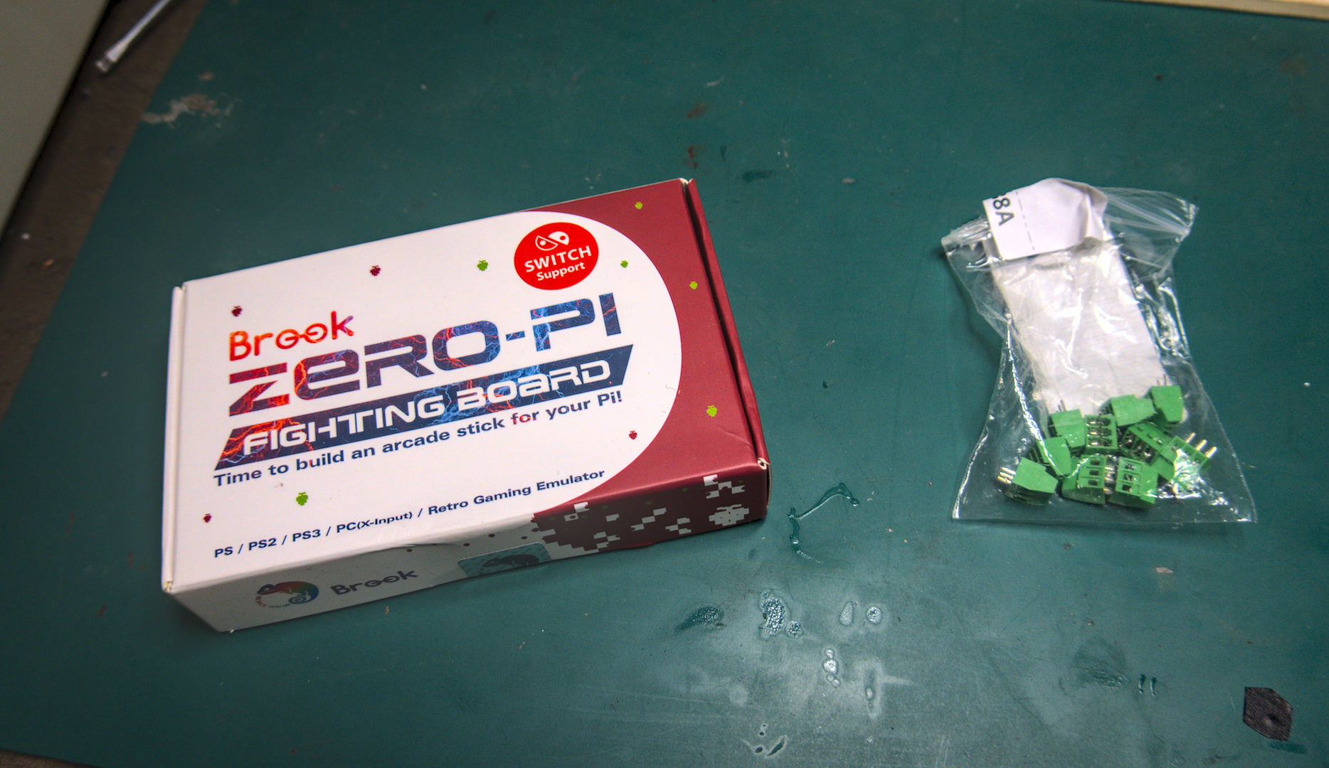
However, this would entail soldering the wiring directly onto the PCB, which occludes the possibility of upgrades later on - and if any wire or button becomes damaged, replacement would become quite difficult. One solution would be to simply buy the Brook wiring kit and hitbox harness, but that would run nearly $40. So in order to save as much money for my client as possible, I decided I would simply solder the screw in terminals myself.
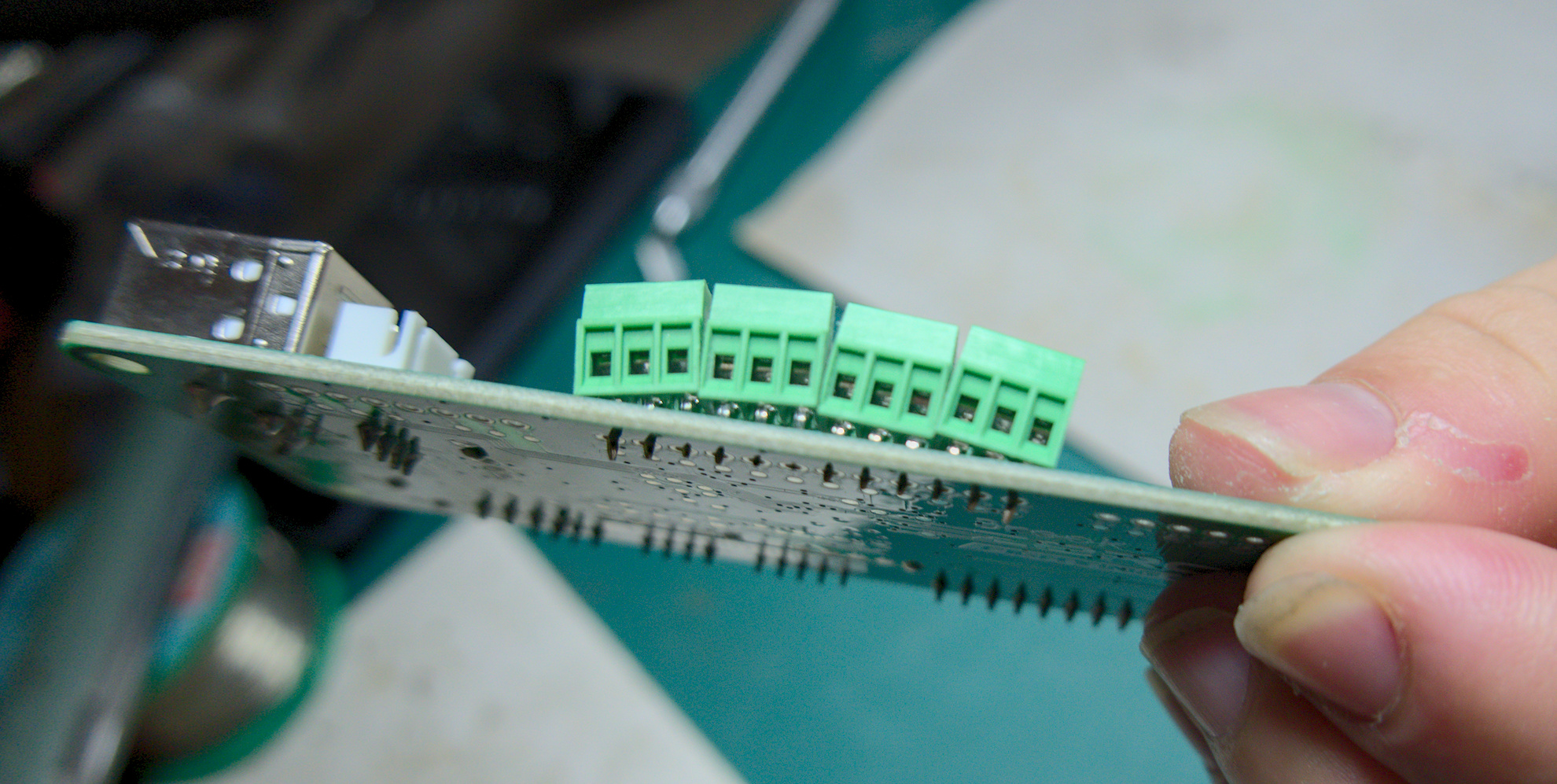
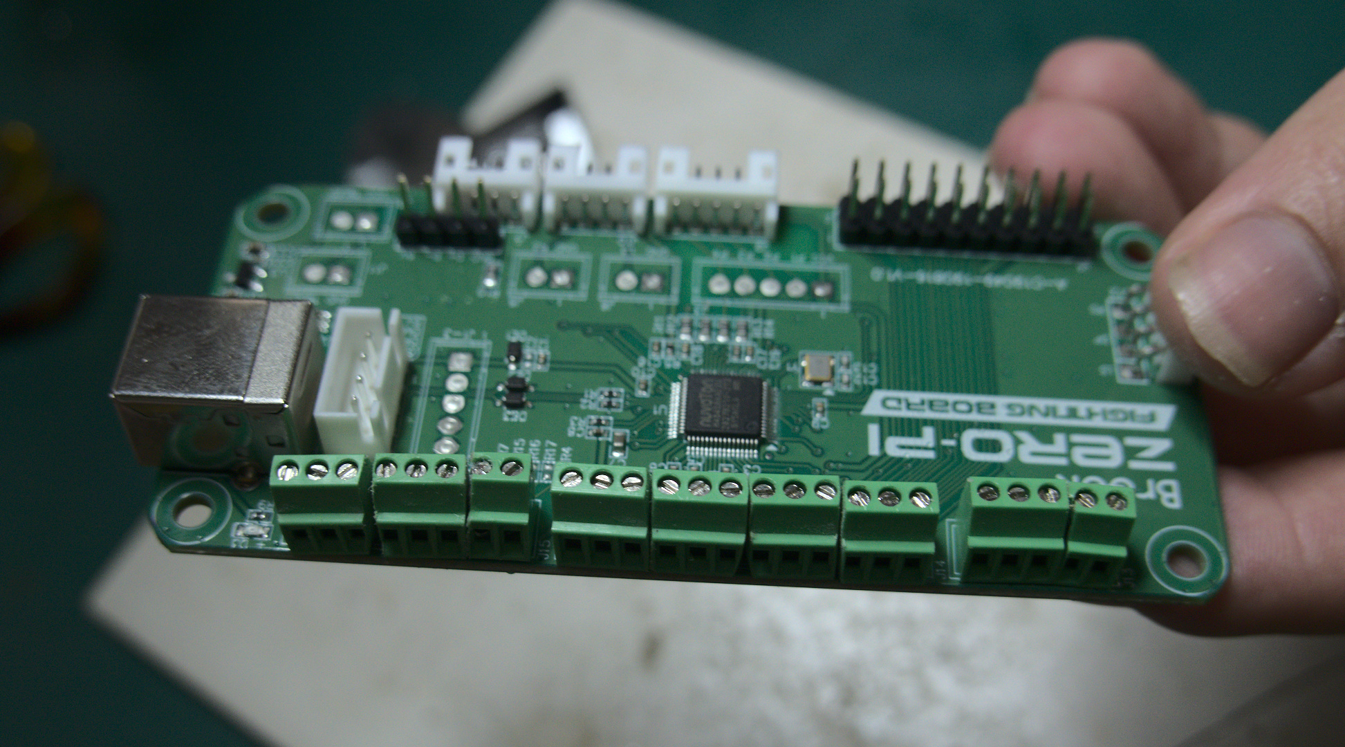
However, there are a couple of problems with this approach. While the correct terminal type was easy to find, the KF128-2.54mm, the first and most obvious issue is that the pass-throughs of the Brook Zero Pi are split into an awkward pin configuration - 5/12/8. Sharing no common denominator, it wouldn't be possible to simply purchase a set of screw-in terminals and align them naturally.
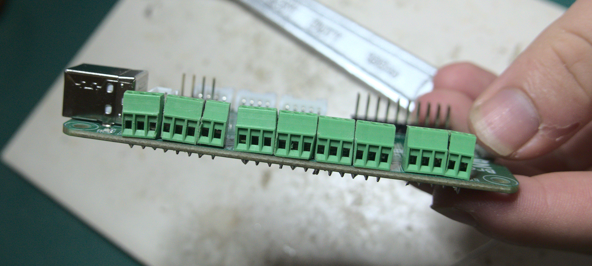
Secondly, even if there was a common denominator, when slotting the terminals into the through holes, these 2.54mm terminals are too large to sit next to each other, pushing each other apart and creating an arch.

The naive solution would be to simply purchase 3 screw-in terminal sets in the right pin lengths. But this is expensive, since no online retailer will sell them to you in singles. Purchasing them this way would cost around $25.
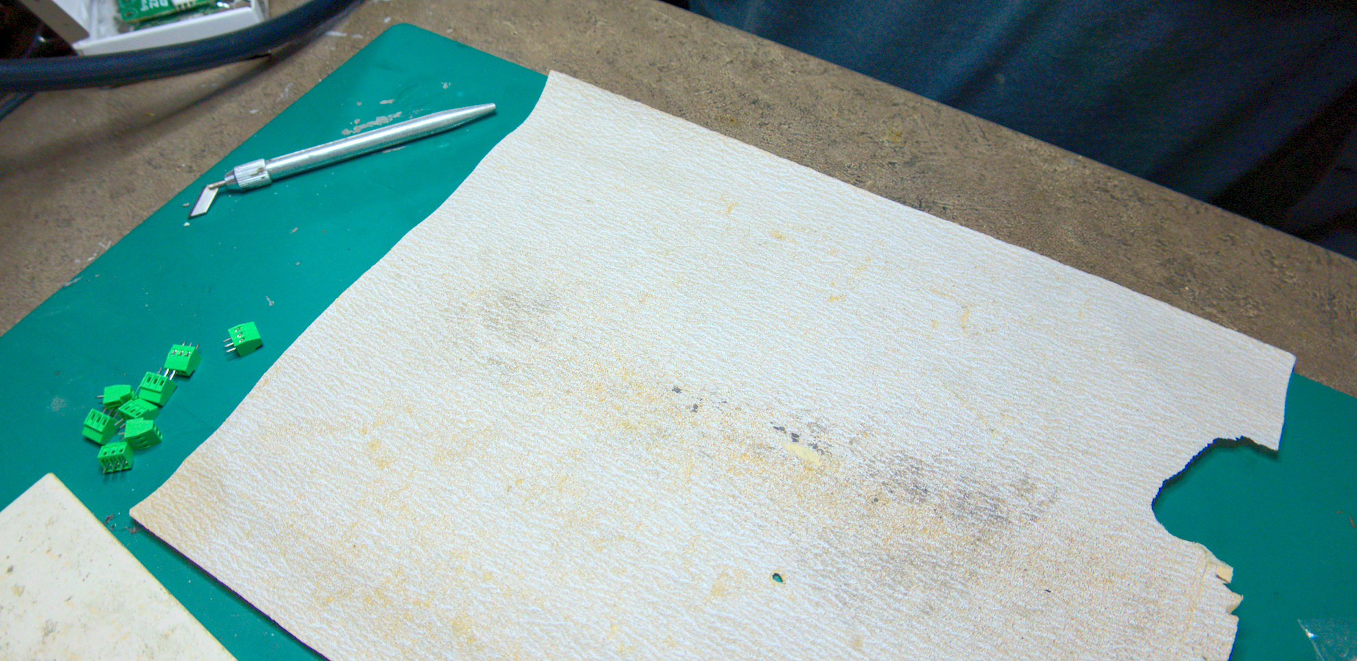
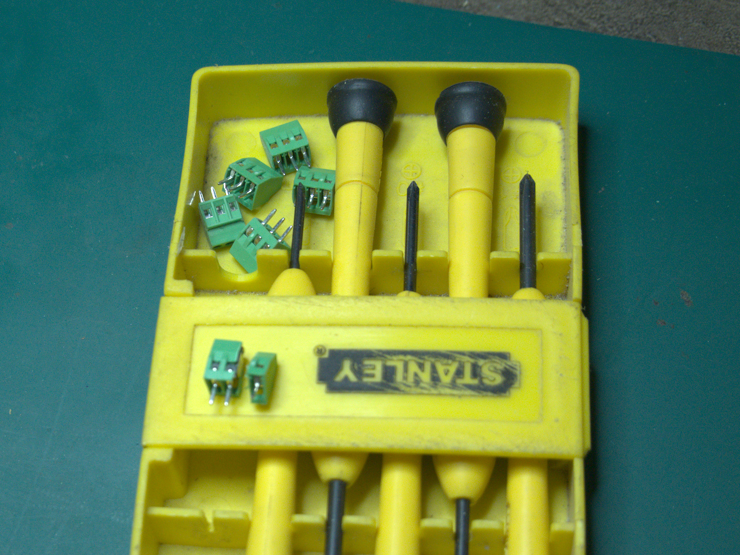
Instead, I purchased 10 3-pin terminals for $11 - providing a total of 30 pins. Since the conductors inside are constructed as a single piece - the plastic enclosures mostly serve to provide structure and prevent the conductor from turning with the screw - it's possible to just cut the terminals apart and use them individually, simply split them at the seam with a small knife. From there, you merely need to sand down their sides until they sit snugly next to each other on the board.
With all the terminals prepared, it's a trivial matter to solder them into place. With this, I saved my client about $20, using only a modicum of extra handiwork.
Overall, I'm quite satisfied with the results, particularly the soldering job, since it's something I do very rarely. However if I could give it another go, I'd construct a small jig to hold the terminals tight and neat while I solder them in place. While functional, their current layout leaves a lot to be desired aesthetically. For now, this will have to do.
Sidenote: Do not try to super glue the terminals into distinct blocks ahead of time, to keep it neat. It WILL gum up the conductor component and prevent the terminal from screwing open/closed neatly. Luckily I bought spares!